In the previous section "Heating a fluid flow in a pipeline" using the graoanalytical method used in the applet, or manually (using the above formula), we could determine the required heat output for heating the fluid flow in the pipeline. In this section, we will develop the topic and define the design characteristics of the pipeline for transferring such heat power to a given fluid flow. Thanks to the graphic-analytical method, it is possible to optimize all the parameters involved in the calculation by moving along the corresponding axes of the nomograms, i.e. starting from the preferred design characteristics pipeline, you can correct the flow or temperature values ??in the second approximation. An interesting option is a pipeline heated by an external electric heat source. In this case, the heat from the source is transferred through the wall pipeline for fluid flow. This design can be conventionally called a heat exchanger or part of a heat exchanger.
So, let's make a heat balance equation, equating the amount of energy [thermal power] transferred from the pipeline walls to the fluid flow, and the amount of energy [thermal power] that must be imparted to the liquid to heat it to a given temperature.
Let's work out the equation of thermal balance:
L · P · a · dTn = G · Cp · (Tout-Tin), [1]
where
a – convective heat exchange coefficient, W/(m2·К);
L – length of a heated up site of the pipeline, m;
P – perimetre of a flow section of the pipeline, m;
dTn – temperature pressure, К;
Tin, Tout – Fluid temperature on an inlet and an exit of a heated up site of the pipeline, K;
G – The mass rate of flux of a fluid, kg/s;
Cp – specific heat capacity of a fluid, J/(kg·К).
Substituting in (1) expression for an arithmetic-mean temperature head at temperature of wall Tw:
dTn = [Tout - Tin]/ln[(Tw-Tin) / (Tw-Tout)], [2]
let's gain the formula for definition of length of a section of heating: :
L = G · Cp · ln[(Tw-Tin)/(Tw-Tout)] / (a · P). [3]
The circuit design of nomographs is presented in drawing 1.
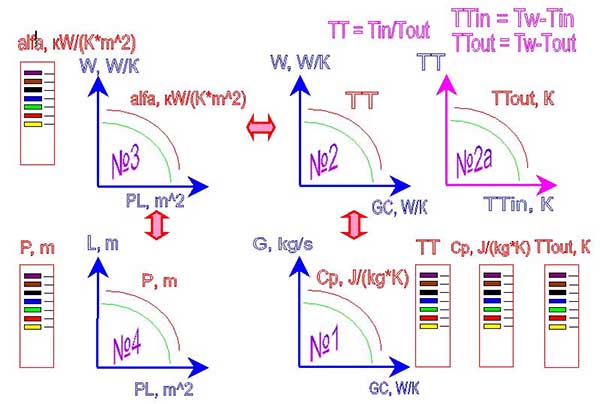
Drawing 1. The circuit design of system of nomographs
After applet start an auxiliary window will have the following appearance (drawing 2).
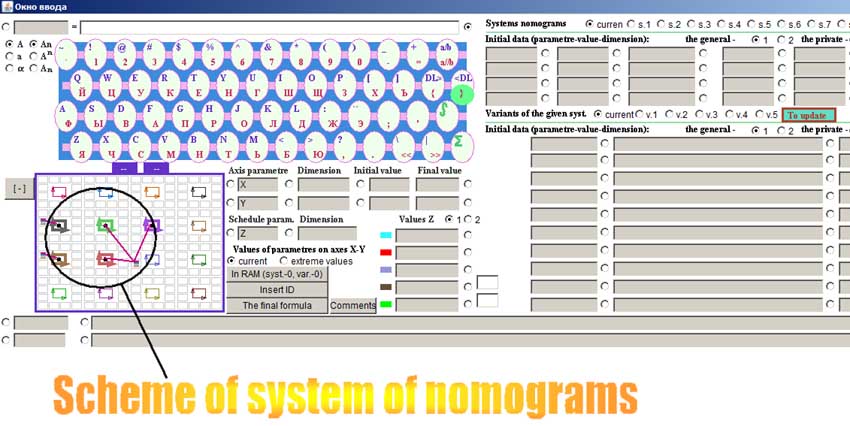
Drawing 2. An additional window of an applet on build-up of system of nomographs
In an auxiliary window the circuit design of disposing of nomographs is already shown, but she demands recurring feeding into, therefore on each small square which is marking out a nomograph "is clicked" by the right key of the mouse and the left key "clicked"on that place where there should be a colour flag indicator (a place of disposing of meaning of parametre Z of a nomograph). It is possible choose any other location of variable parametre Z. After recurring appointment of the circuit design of nomographs "is clicked" by the left key of the mouse on sign "[-]", had in left overhead to the angle of the circuit design of nomographs. It will change the aspect on "[+]". It means, that the circuit design of nomographs is fixed. .
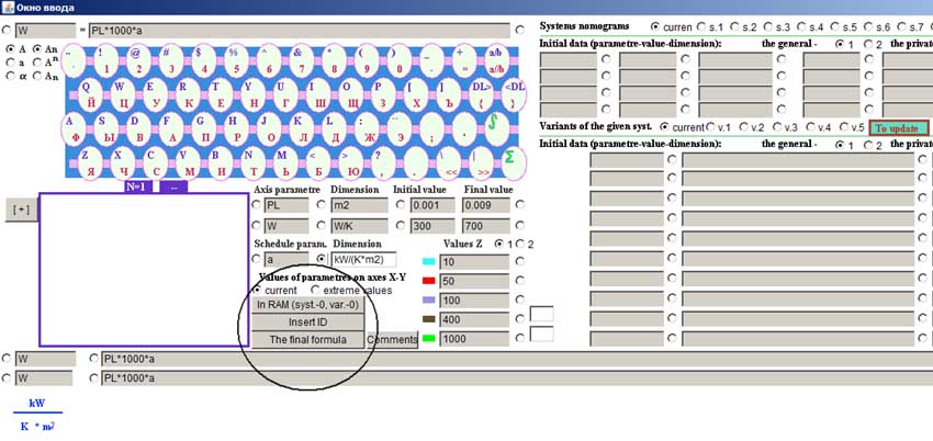
Drawing 3. An additional window of an applet on build-up of system of nomographs with the tuned circuit design of nomographs
After attaching of the circuit design of nomographs, "is in succession clicked" on everyone sign, marking out a nomograph, and it is pushed three buttons "In the working memory" ("В ОЗУ"), "Substitution ID" ("Подстановка ИД"), "the Total formula" ("Итоговая формула") for entering of all parametres of a nomograph into an on-line storage and design formula formation.
We transfer to the basic window and we induct meanings of steps on axes "X" and "Y". We push the button "to Build on ID" ("Построить по ИД").
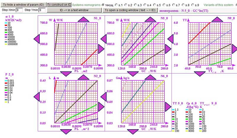
Drawing 4. The basic window of an applet for build-up of system of nomographs.
So, let's assume that we have the whole set of data in the first approximation: there are formulas, there are nomograms, the desired design characteristics of the pipeline are clear, the estimated flow rate is accepted, the temperatures are estimated ...
You can start graphic-analytical calculation or "click" on the calculator. But... And what heat transfer coefficient?! And the heat transfer coefficient is already a separate story, which is devoted to a separate page
"Graphic-analytical calculation of the heat transfer coefficient". So decide on the heat transfer coefficient and go back to evaluate the heat transfer parameters during the flow
liquid (gas) in a pipe or capillary.
Yes! And yet, we are guided by a laminar flow, since with a turbulent flow the technique will have to be complicated. The flow regime in the pipeline (laminar or turbulent) can be assessed by visiting the page
"Graph-analytical calculation of the Reynolds number".
The hydraulic parameters of the heat exchanger can be calculated using the page of our website "Graphic-analytical calculation of the coil (laminar throttle)" (there is also a graph for the straight section).
Suppose that you have calculated everything, for example, taking into account the home water supply network, only you have a low-power source of electrical energy and something does not allow you to increase the power. It is necessary to "clamp" the flow,
so that there is at least a small trickle, but under pressure.
To do this, you need to install the jet. The calculation of the jet is given on the page "Graphic analysis of the jet"
In general, nothing complicated! Unless now you need to give permission to run the applet in your browser ...
More detailed instruction on operation with an applet.
The topic of this section is the calculation of heat transfer when fluid moves in a pipe with an external heat source (calculation of a conditional heat exchanger).
graphic-analytical systems
Copyright © 2005-2022 All rights reserved